Ingeteam has designed and accomplished the commissioning of the following two DP3 Accommodation Vessels for the Mexican shipowner PEMEX.
These vessels have the particularity of having only one retractable thruster powered at the same time from both DP zones (DP1 and DP2).
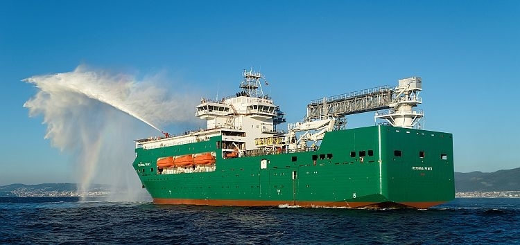
REFORMA PEMEX built at Hijos de J. Barreras Shipyard (Vigo, Spain).
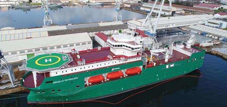
ORGULLO PETROLERO built at Navantia shipyard (Ferrol, Spain).
The main electrical plant Single Line Diagram is as follows:
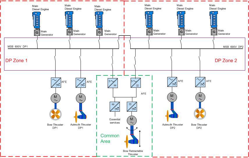
Due to this configuration DNV requires to perform a “live” short-circuit test in order to prove that in case of a failure (fire, flooding, short circuit, …) in the common area it will not be propagated to the DP1 and DP2 main switchboards. As well it is necessary to ensure that in the event of a failure in one zone (DP1 or DP2) it will not be transfered to the other zone through the retractable frequency converter DC bus.
The short-circuit test must fulfil the DNV rules “For DYNPOS-AUTR and DPS 3.
INGETEAM MARINE SYSTEMS SCOPE SUPPLY COMPRISES:
| 3000kVA |
690V |
2510,2A |
Power factor
0,9 |
60Hz |
720rpm |
| 690V MSB DP1 with PMS included |
450V MSB DP1 |
230V MSB DP1 |
115V MSB DP1 |
| 690V MSB DP2 with PMS included |
450V MSB DP2 |
230V MSB DP2 |
115V MSB DP2 |
| 690V ESB EP1 with Emergency and Harbour option included |
115V ESB EP2 |
- 2 x INGEDRIVE LV AFE Frequency converters for propulsion thruster DP1 and DP2:
| 2700kW |
Input voltage
690V |
Output voltage
0 upt to 690V |
Efficiency at 100%
96% |
Input current
2503A |
Output current
2831A |
- 2 x INGEDRIVE LV AFE Frequency converters for tunnel thruster DP1 and DP2:
| 1500kW |
Input voltage
690V |
Output voltage
0 upt to 690V |
Efficiency at 100%
96% |
Input current
1391A |
Output current
1547A |
- 2 x INGEDRIVE LV AFE Frequency converters for retractable thruster:
| 1500kW |
Input voltage
2 x 690V |
Output voltage
0 up to 690V |
Efficiency al 100%
96% |
Input current
2 x 1390A |
Output current
1547A |
- 2 x Induction AC motor for propulsion thruster DP1 and DP2:
| 2700kW |
690V |
2643A |
Power factor 100%
90% |
Efficiency at 100%
96% |
- 2 x Induction AC motor for tunnel thruster DP1 and DP2:
| 1500kW |
690V |
1470A |
Power factor al 100%
90% |
Efficiency al 100%
96% |
- 1 x Induction AC motor for retractable thruster:
| 1500kW |
690V |
1470A |
Power factor at 100%
90% |
Efficiency at 100%
96% |
SHORT-CIRCUIT LIVE TEST CONFIGURATION
The following scenario, during DP mode operation, was tested and approved by DNV and the FMEA. The vessel was operated in DP with:
- Two main generators connected with approximately the 50% of the load.
- Main propulsion DP1 and DP2 connected and running at 20%.
- Bow thruster DP1 and DP2 connected and running at 20%.
- Both Retractable thruster incomings from DP1 and DP2 connected.
- All the general services for the electrical plant working on operation.
Both 690V bus-ties were in closed position.
A three phase short-circuit was done in MSB 690V closing the CB of the short-circuit box which was connected directly to the MSB.
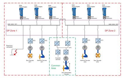
The box was designed and manufactured by INGETEAM MARINE SYSTEMS and used in both vessels.
- With two generators connected at the same time, it is possible to check the non-lost of synchronism between them after the short-circuit.
SHORT-CIRCUIT SIMULATION AND RESULTS
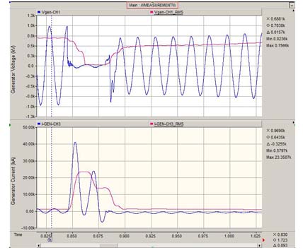
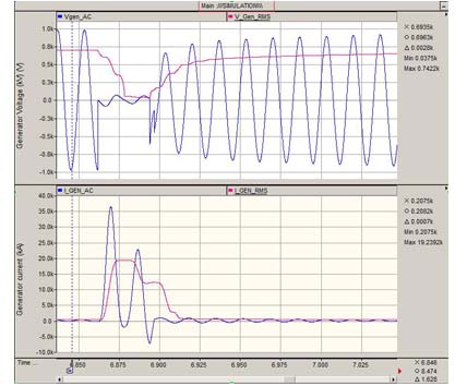
The goal of the test was to check that with the settings of the systems involved (breakers settings, AVR settings, governor settings,…) only the selected breaker (the one that produced the short-circuit and identical to the retractable thruster) was tripped and all the main consumers continued working.
To check the performance of the plant and the ride through capability the following measurements were checked:
- Voltage and frequency drop in the net (register measuring bus bars).
- The overvoltage and overfrequency in the net.
- Short-circuit current on the main generators (with an oscilloscope and rogosky probes).
- DC bus voltage of the FC.
- Possible trip of any consumer connected to the network.
Real measurement performed on board:
Simulation:
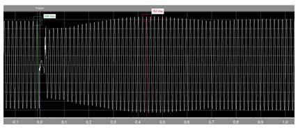
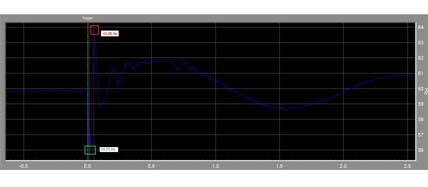
On the other hand, the input voltage and frequency resulted equal were the same in the four running frequency converters.
- Graph: Frequency converter input voltage:
- Graph: Frequency converter input frequency:
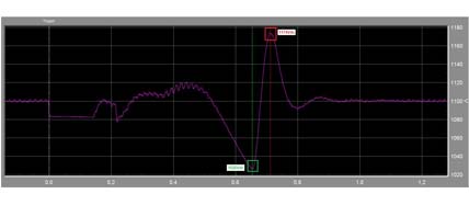
The coasting mode was correctly accomplished in the four frequency converters in operation, according to the following graph DC bus voltage which resulted within the limits all the time:
- Overvoltage DC Bus setting: 1210Vdc
- Undervoltage DC Bus setting: 875Vdc
DC bus voltage:
CONCLUSIONS
As conclusion of this test it should be demonstrated that in case of a short-circuit:
- The main electrical plant remains in operation, main generators and FC CBs connected and running.
- All main auxiliary equipment necessary to maintain the DP position are not affected.